Layout Setup for C&I PV Plant
For a C&I PV plant, it is recommended to complete the layout setup by importing an Excel layout file.
-
Create an Excel layout file (skip this step if one is already created).
Note: To obtain the Excel layout template, use one of the following download methods:
- Clickhttps://file.isolarcloud.com/template/optimizer_sn_import/optimizer_sn_import_template_en_US.xlsx to download the template.
- On the Layout Settings page, click
Import Layout File and then click
Click to Download Template.
- On the Layout Settings page, click
 next to Import Layout File
and choose Download Template.
next to Import Layout File
and choose Download Template.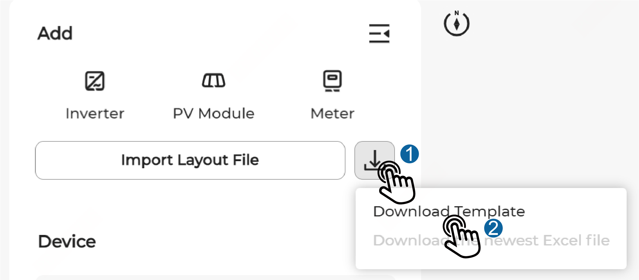
Follow the instructions on the Demo sheet to fill in layout data on the Layout sheet based on the actual physical layout of the plant.Notice: You must strictly follow the instructions in the Excel template. The Demo sheet cannot be modified or adjusted.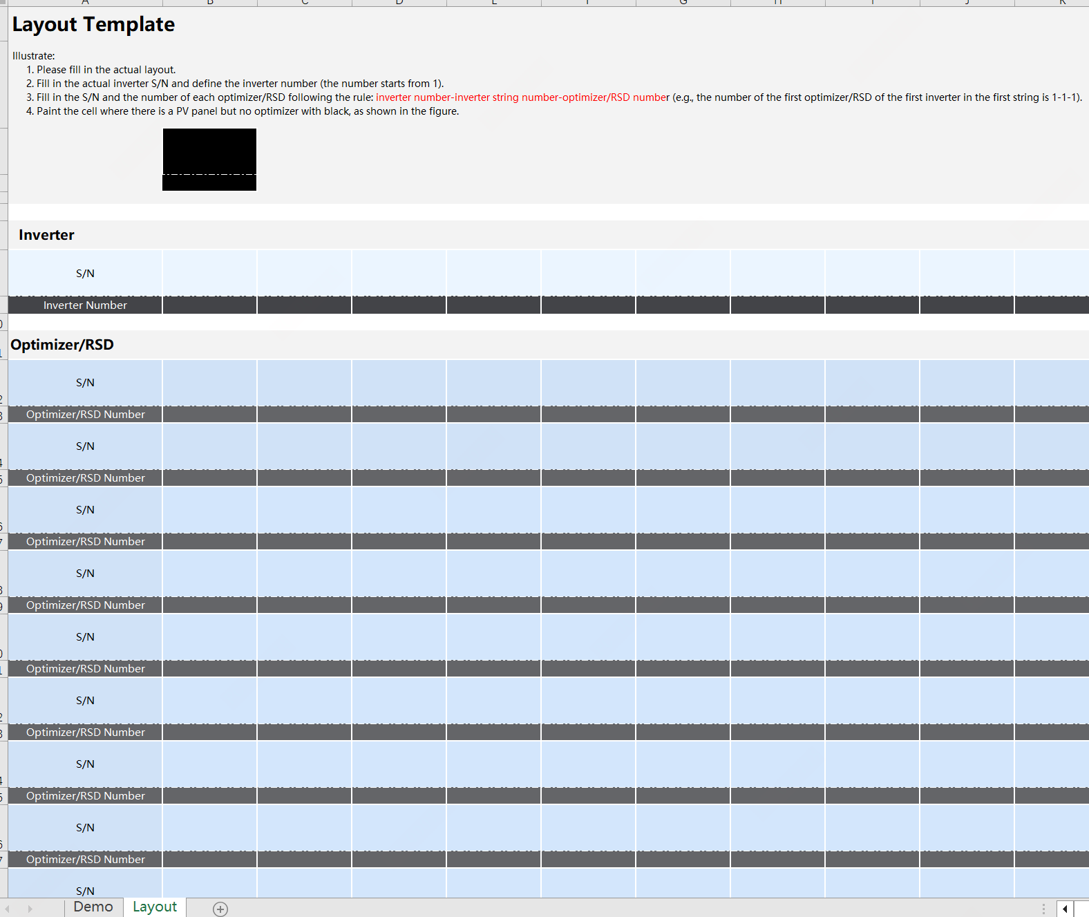
-
Fill in the inverter S/N and assign a number to the inverter (starting from 1).
-
Fill in the S/N and number of each optimizer/RSD. Follow the following format for the optimizer/RSD number: inverter number-inverter string number-optimizer/RSD number (e.g., the number of the first optimizer/RSD of the first inverter in the first string is 1-1-1).Note: In 2-in-1 optimizer/RSD scenarios where two modules are connected to a single optimizer/RSD, fill the same optimizer/RSD S/N and optimizer/RSD number for both modules in the Excel template.Note: It is recommended to use a QR code scanner to fill the optimizer/RSD S/N. Scan the QR code on the label of a device to automatically fill the S/N in the corresponding position of the Excel template.
- For the optimizer/RSD S/N and optimizer/RSD number, you can add rows and columns based on actual needs (up to 1000 rows and 1000 columns).
Notice: After completing the layout file, check against the following checklist to prevent import or parsing failures:- The inverter S/N and inverter number cannot be empty or duplicated. The inverter number must be a number.
- The optimizer/RSD S/N and optimizer/RSD number cannot be empty or duplicated. The S/N must be 11 digits in length and cannot contain spaces.
- The imported Excel file cannot be empty or encrypted, or contain formulas.
- The same S/N cannot be contained on multiple canvases.
- No more than 35 optimizers/RSDs can be connected to a single string.
- The string number contained in the optimizer/RSD number cannot exceed 36.
-
Import the Excel layout file.
Note: Before importing the layout file, please set the Optimizer/RSD-module ratio to the actual ratio for the current layout. In 2-in-1 optimizer/RSD scenarios where two modules are connected to a single optimizer/RSD, set the Optimizer/RSD-module ratio to 1:2.
To set the Optimizer/RSD-module ratio, click
 > Edit,select an appropriate Optimizer/RSD-module
ratio in the Edit Physical Layout
window, and then click Confirm.
> Edit,select an appropriate Optimizer/RSD-module
ratio in the Edit Physical Layout
window, and then click Confirm.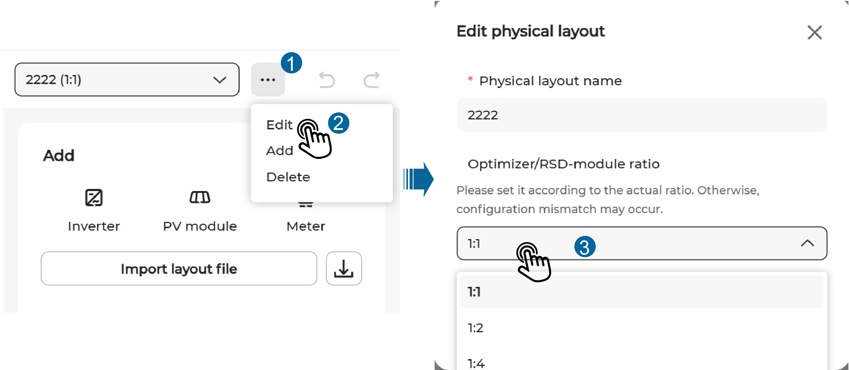
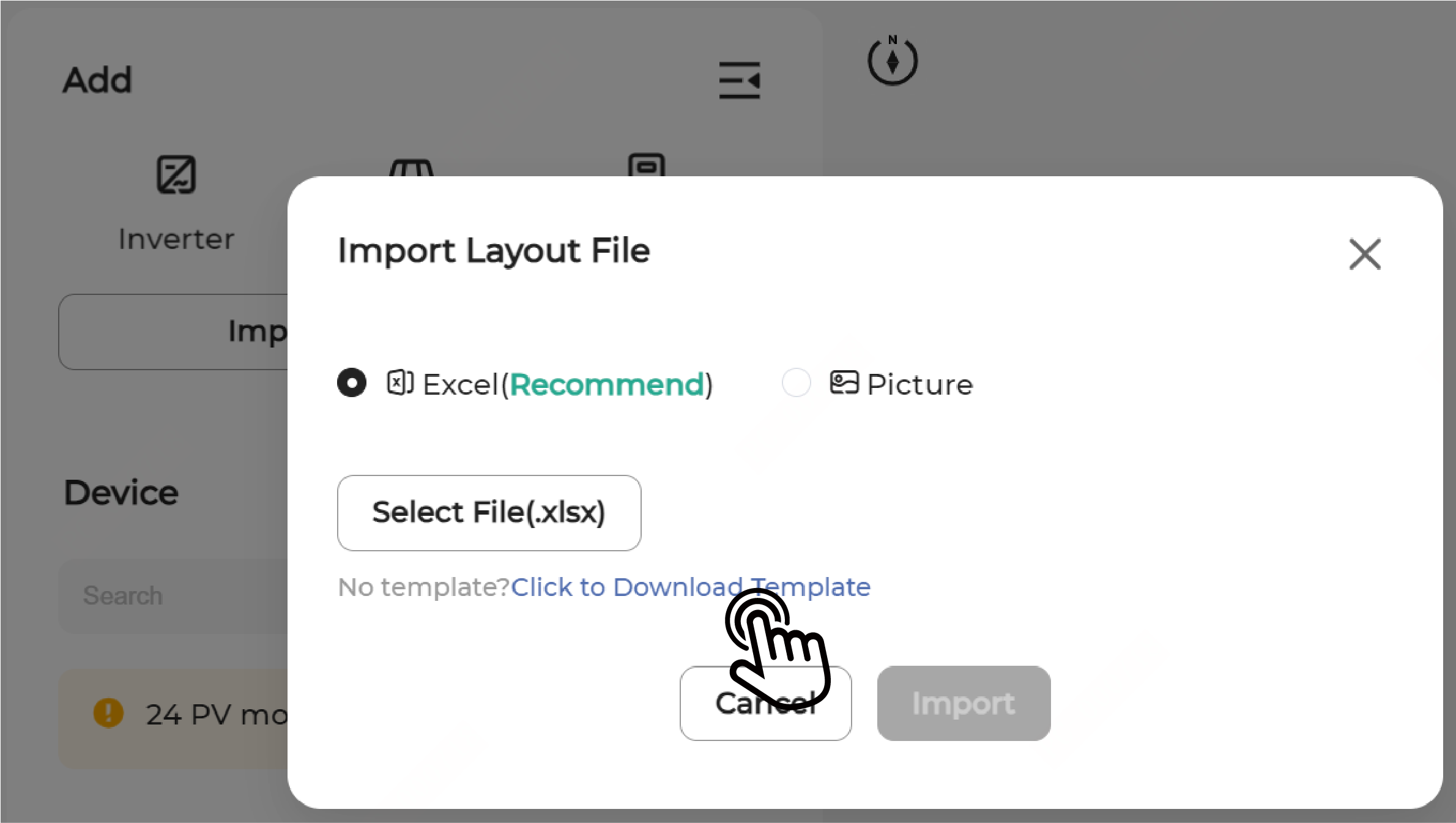
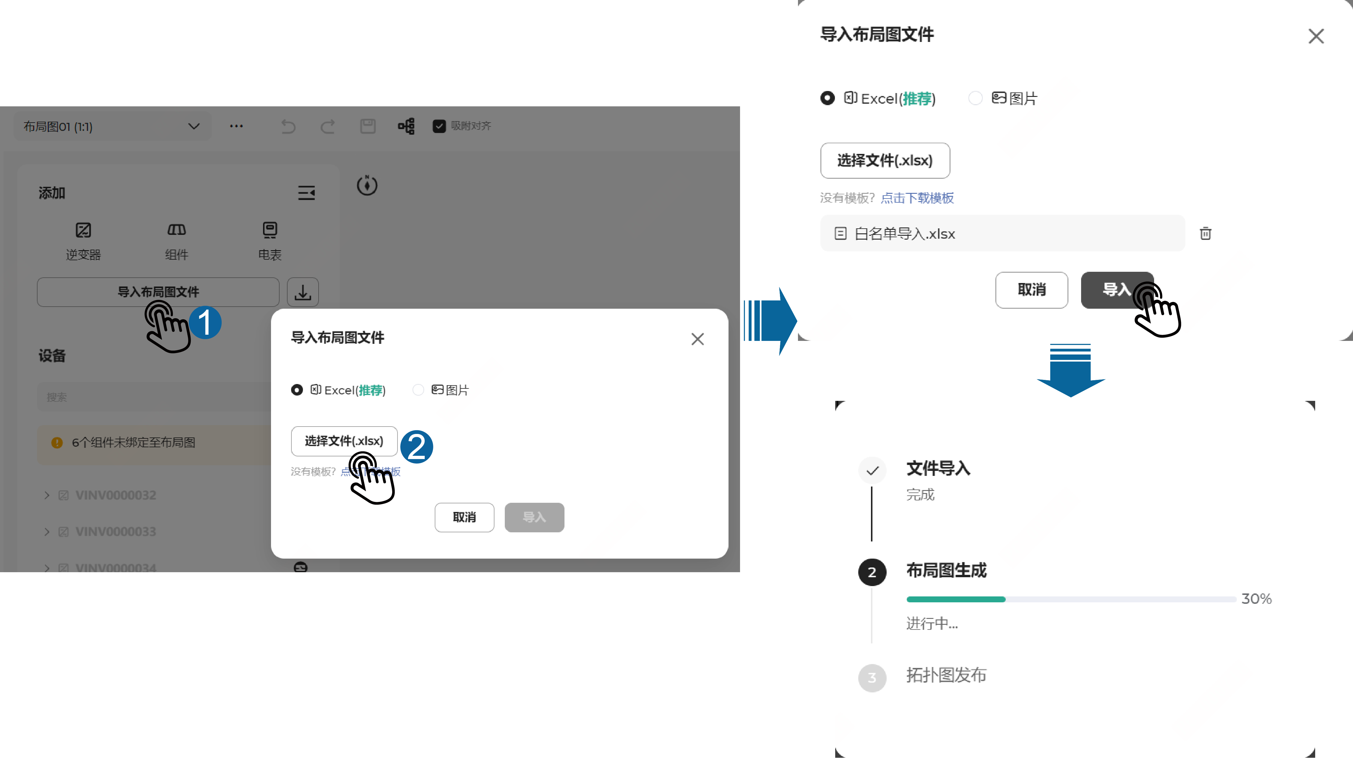
Click Import Layout File. In the Import Layout File pop-up window, choose Excel, click Select File(.xlsx), select the file to be imported, and then click Import. The import progress of the layout file will be displayed on the page.
-
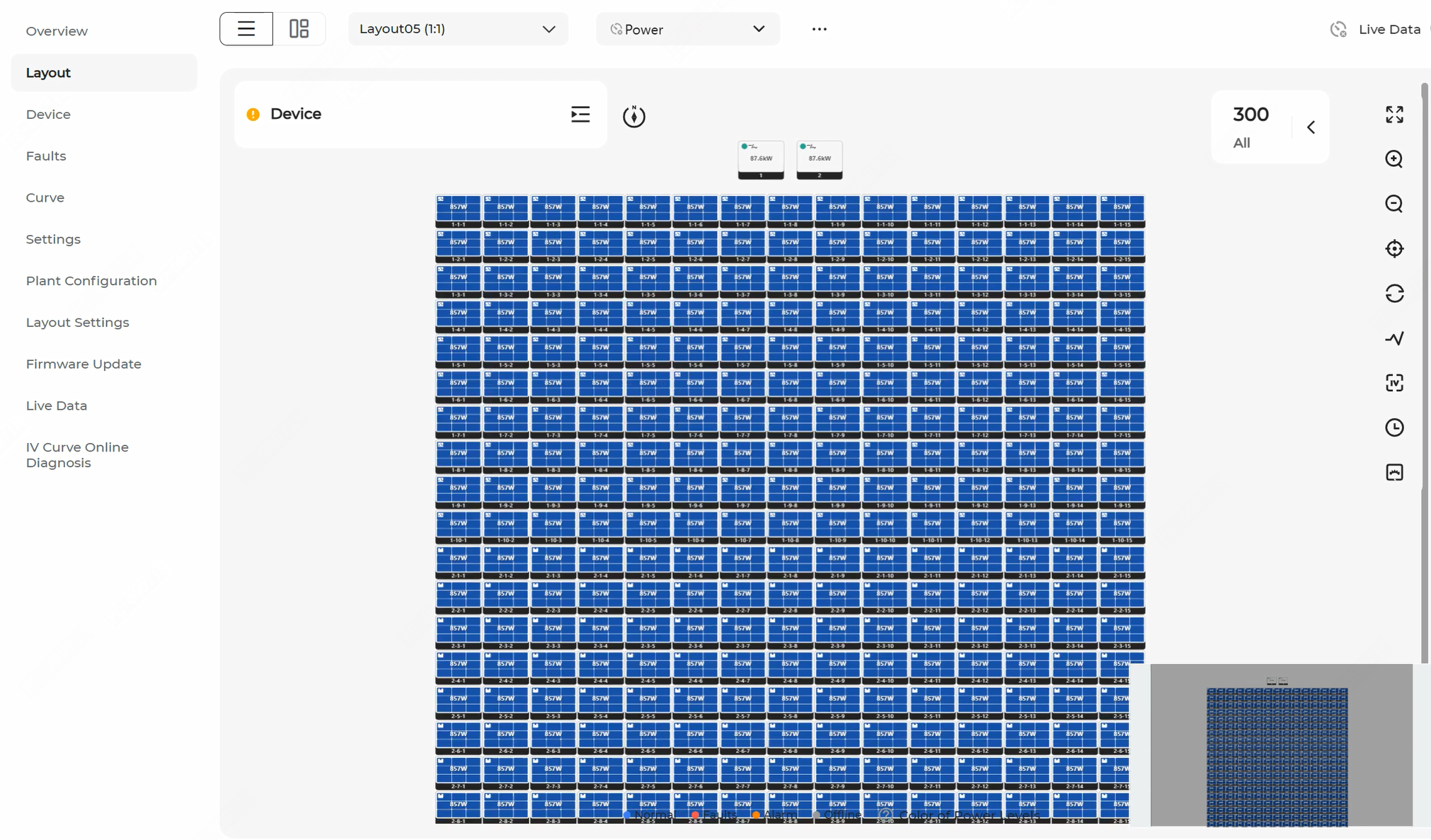
View import results and handle exceptions.
After the import is complete, the system returns the Layout import successful message and redirect to the Layout page. You can view the imported layout.
 Take corresponding measures to handle exceptions.
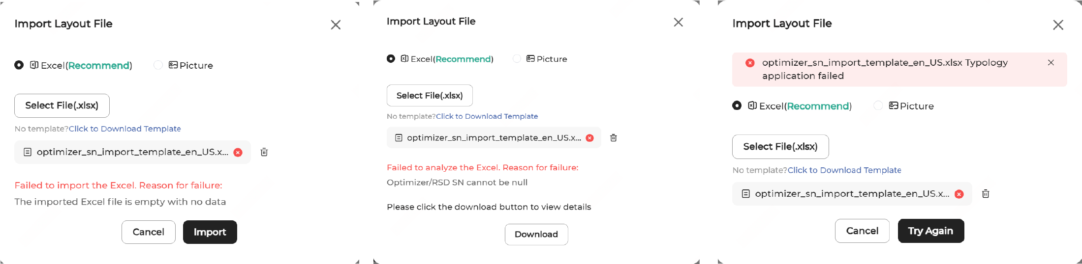
- If the Excel layout file fails to be imported or parsed, the failure reason will be displayed in the Import Layout File pop-up window. Modify the file accordingly and re-import it.
- To view details about the file that failed to be parsed for quick troubleshooting, click Download.
- If the topology fails to be applied, a prompt will be displayed in the pop-up window. Try again or try another file.
-
If a module fails to be recognized, manually add the module and associate an
optimizer/RSD S/N with it:
-
Drag and drop the icon
 to the layout. Then, fill in
the module information such as Row,
Column, Azimuth Angle,
and Tilt Angle, and click
Confirm.
to the layout. Then, fill in
the module information such as Row,
Column, Azimuth Angle,
and Tilt Angle, and click
Confirm.
-
Click the module, and click Assign. Then, select
the S/N of the corresponding optimizer/RSD to associate it with this
module.
-
Drag and drop the icon
-
Set up the logical layout:
-
Click
 to select the
inverter and string to be set.
to select the
inverter and string to be set.
- Click to drag the modules and arrange them in the correct order based on the actual wiring of the optimizers/RSDs, and then click Complete.
- In case modules are arranged incorrectly, right-click a module and choose Clear. After confirmation, the optimizer/RSD numbers of the current and subsequent modules will be cleared.
-
Click
-
Re-import the layout file if there are changes to the devices in the
plant.
Notice: Re-importing the layout file for a layout will clear all current settings of the layout.
You can download the most recently uploaded history file by using one of the following methods, make adjustments, and then re-import it.
- Click Import Layout File and then click
.
- Click
next to Import Layout File and choose
Download the newest Excel file.
- Click Import Layout File and then click
-
After completing the layout setup, tap
 in the upper right corner of the page
to publish the layout.
Note: If you do not want to publish the layout immediately, you can click
in the upper right corner of the page
to publish the layout.
Note: If you do not want to publish the layout immediately, you can click to save the current layout
settings.
to save the current layout
settings. -
If a plant is geographically scattered, add multiple layouts for the
plant.
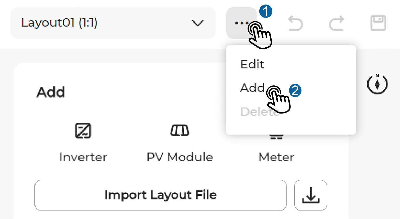
Click at the top
of the page, choose Add, set the Physical
Layout Name and Optimizer/Module Ratio,
and then click Confirm.