Power Factor Control
Used to adjust the power factor to reduce the power factor adjustment charges.
- Choose Energy management > Grid-connected reactive power.
-
Set Function enable/disable.
-
Enable: Enable the reactive power control function. Proceed to subsequent configurations.
-
Disable: Disable the reactive power control function.
-
- Choose Power factor control in Mode selection.
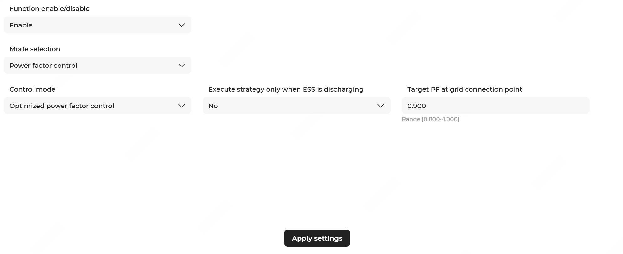
- Choose a Control mode.
- In Optimized power factor control mode (default), configure the following parameters:
Parameter Description Execute strategy only when ESS is discharging - Yes: When the grid power factor decreases, the power factor control strategy will only be executed during discharging of the ESS.
- No: When the grid power factor decreases, the power factor control strategy will be executed during charging, discharging, and zero power output of the ESS.
Power factor target value Range: 0.800–1.000; 0.900 by default. When the power factor falls below the set value, the system will automatically calculate the reactive power target value based on this target value and the active power at the grid connection point, and coordinate with the PV-ESS system for reactive power regulation.
- Normal mode: The power factor can be set with a positive or negative
sign, and the following parameters need to be configured.
Parameter Description Execute strategy only when ESS is discharging - Yes: When the grid power factor decreases, the power factor control strategy will only be executed during discharging of the ESS.
- No: When the grid power factor decreases, the power factor control strategy will be executed during charging, discharging, and zero power output of the ESS.
Power factor target value Range: -1.000– - 0.800 or 0.800–1.000; 0.900 by default.
If the absolute value of the power factor is less than the set target value, the target reactive power value of the grid-connection point can be calculated on the basis of the set target value and the active power value of the grid-connection point, and then the reactive power can be regulated by the ESS and PV system.
Note: When the directions of reactive power and active power are the same, the power factor is positive; when the directions of reactive power and active power are opposite, the power factor is negative.Power factor control deadband Define the allowable fluctuation range for the target power factor value. Range: 0.001–0.200; 0.010 by default.
- Four-quadrant control mode: This mode supports setting different
power factor values for charging and discharging. The following parameters
need to be configured:
Parameter Description Execute strategy only when ESS is discharging - Yes: When the grid power factor decreases, the power factor control strategy will only be executed during discharging of the ESS.
- No: When the grid power factor decreases, the power factor control strategy will be executed during charging, discharging, and zero power output of the ESS.
Charging power factor target value Range: -1.000– - 0.800 or 0.800–1.000; 0.900 by default.
If the absolute value of the charging power factor is less than the set target value, the target reactive power value of the grid-connection point can be calculated on the basis of the set target value and the active power value of the grid-connection point, and then the reactive power can be regulated by the ESS and PV system.
Note: When the directions of reactive power and active power are the same, the power factor is positive; when the directions of reactive power and active power are opposite, the power factor is negative.Discharging power factor target value Range: -1.000– - 0.800 or 0.800–1.000; 0.900 by default.
If the absolute value of the discharging power factor is less than the set target value, the target reactive power value of the grid-connection point can be calculated on the basis of the set target value and the active power value of the grid-connection point, and then the reactive power can be regulated by the ESS and PV system.
Note: When the directions of reactive power and active power are the same, the power factor is positive; when the directions of reactive power and active power are opposite, the power factor is negative.Power factor control deadband Define the allowable fluctuation range for the target power factor value. Range: 0.001–0.200; 0.010 by default.
- In Optimized power factor control mode (default), configure the following parameters:
- Click Apply settings. In the pop-up window, enter the Task name, set the Instruction valid period, and click Confirm.